Tube drawing with ultrasonic vibration
Tube Drawing With Ultrasonic Vibration
The application of ultrasonic technology to cold-drawn seamless steel pipes or other metal plastic processing is a new development in the application of high-power ultrasonics in the 1970s. In August 1978, the Shanghai Municipal Science and Technology Commission formally issued a scientific research task, which was undertaken by Shanghai Steel Pipe Factory. The Institute of Acoustics of the Chinese Academy of Sciences and Shanghai Ultrasonic Instrument Factory collaborated to conduct ultrasonic cold drawn seamless steel pipe tests.
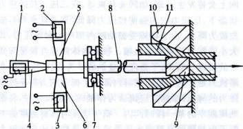
Cold drawing of the pipe under the condition of applying ultrasonic vibration to the pipe drawing die or mandrel or both. The principle of ultrasonic vibration extubation is to convert high-frequency electrical resonance into mechanical vibration through a transducer, and propagate the vibration energy to the deformation zone through the concentrator, changing the nature and stress state of metal deformation. The practical sound transmission system of the external vibration model is shown in Figure 1. The use of this sound transmission system is to facilitate mold change and not increase the length of the hammer head. The sound transmission system of the vibrating mandrel is shown in Figure 2
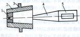
Figure 1 Practical sound wave transmission system
1 an outer mold; 2 a jacket; 3 fixed points; 4 concentrator; 5 a vibrator
1, 2, 3-transducer; 4, 5, 6-concentrator; 7-pressure bearing 8-tie rod; 9-mandrel; 10-outer mold; 11-tube material
Figure 2 Ultrasonic vibration mandrel system when drawing the inner convex rib tube
The vibrator, one of the transducer components, is made of laminated nickel sheets. The use of magnetic materials under the action of an external magnetic field produces tiny macroscopic deformations that stretch and shrink in one direction, and may also produce volume shrinkage or expansion (magnetostrictive effect), turning high-frequency electrical resonance into mechanical vibration. The equivalent circuit of the magnetostrictive transducer in working condition is shown in Figure 3. In the dashed box on the left side of the figure is the output equivalent circuit of the ultrasonic generator, which is composed of high-frequency sinusoidal excitation power e'and internal impedance z'; in the dashed box on the right is the equivalent circuit of the transducer, z1', z2' is the clamp impedance and dynamic impedance respectively.
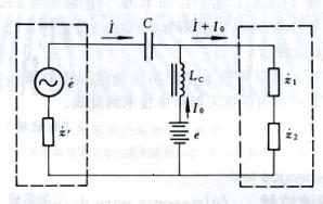
Figure 3 Equivalent circuit
The current flowing in the transducer is the sum of the excitation current I and the polarization current I0. I0 is a constant constant provided by the DC power supply e, and the excitation current I is a sinusoidal alternating variable. The resistance of the reactor Lc to I0 is very small, but the resistance to I is very high. The coupling capacitor C only allows I to pass, but not I0, so the current flowing in the transducer is I and I0. I0 generates a polarizing magnetic field in the core of the transducer, and I generates an excitation magnetic field. The concentrator is a cone whose length is distributed according to the amplitude so that the end point has the largest amplitude and the smallest stress (Figure 4).
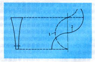
1-stress; 2-amplitude
Figure 4 Stress and amplitude distribution on the concentrator
The effects of using ultrasonic vibration to pull the pipe are: it can reduce the drawing force, increase the deformation of the pass, improve the surface quality of the product, and reduce the residual stress in the empty pipe; it can reduce the requirement for lubricant, increase the life of the tool, and reduce the broken ends and waste. (Improve the yield); can process difficult-to-deform materials and reduce energy consumption.
Researchers put forward three opinions on the mechanism of vibration effect:
(1) Volume effect refers to the absorption of ultrasonic energy to change the state of the organization, resulting in a reduction in the deformation resistance of the metal and an improvement in the plastic processing performance.
(2) Surface effect refers to changing the friction state between the metal and the tool during drawing, reducing the external friction resistance, separating the contact surface, heating the surface, facilitating the suction and discharge of lubricant, purifying the surface, and reversing friction.
(3) The swaging effect refers to a high-frequency alternating stress acting on the metal, which can reduce the deformation resistance.

