ASTM A803/A803M Stainless Steel Feedwater Heater Tubes
ASTM A803/A803M
Standard Specification for Seamless and Welded Ferritic Stainless Steel Feedwater Heater Tubes
1. Scope*
1.1 This specification covers seamless and welded ferritic stainless steel feedwater heater tubes including those bent, if specified, into the form of U-tubes for application in tubular feedwater heaters.
1.2 The tubing sizes covered shall be 5 ⁄ 8 to 1 in. [15.9 to 25.4 mm] inclusive outside diameter, and average or minimum wall thicknesses of 0.028 in. [0.7 mm] and heavier.
1.3 The values stated in either SI units or inch-pound units are to be regarded separately as standard. Within the text, the SI units are shown in brackets. The values stated in each system may not be exact equivalents; therefore, each system shall be used independently of the other. Combining values from the two systems may result in non-conformance with the standard.
2. Referenced Documents
2.1 ASTM Standards:
A480/A480M Specification for General Requirements for Flat-Rolled Stainless and Heat-Resisting Steel Plate,Sheet, and Strip
A763 Practices for Detecting Susceptibility to Intergranular Attack in Ferritic Stainless Steels
A941 Terminology Relating to Steel, Stainless Steel, Related Alloys, and Ferroalloys
A1016/A1016M Specification for General Requirements for Ferritic Alloy Steel, Austenitic Alloy Steel, and Stainless Steel Tubes
3. Terminology
3.1 Definitions—For definitions of terms used in this specification, refer to Terminology A941.
4. Ordering Information
4.1 It is the responsibility of the purchaser to specify all requirements that are necessary for material under this specification. Such requirements may include, but are not limited to,the following:
4.1.1 Quantity (length or number of pieces),
4.1.2 Material description (seamless or welded),
4.1.3 Dimensions (outside diameter, wall thickness (minimum or average wall), and length),
4.1.4 Grade (chemical composition) (Table 1), and
4.1.5 U-bend requirements, if order specifies bending,U-bend schedules or drawings shall accompany the order.
4.2 Optional Requirements—Purchaser shall specify whether annealing of the U-bends is required or whether tubes are to be hydrotested or air-tested (see 10.6).
4.3 Supplementary Requirements—Purchaser shall specify on this purchase order ifmaterial is to be eddy-current tested in accordance with Supplementary Requirement S1 or S2, and if special test reports are required, under Supplementary Requirement S3, and,
4.4 Any additional special requirements.
5. General Requirements
5.1 Material furnished to this specification shall conform to the applicable requirements of the latest published edition of Specification A1016/A1016M unless otherwise provided herein.
6. Materials and Manufacture
6.1 The tubing shall be manufactured by either the seamless or welded process.
6.2 Seamless Tubing:
6.2.1 Seamless tubing shall be supplied from a cold finish process. Hot finishing as the final sizing process is not allowed.
6.3 Welded Tubing:
6.3.1 The tube shall be made from flat-rolled steel by an automatic welding process with no addition of filler metal.
6.4 Surface contaminants may have detrimental effects on high temperature properties or corrosion resistance of tubing. Contamination by copper, lead, mercury, zinc, chlorides, or sulfur may be detrimental to stainless steels. The manufacturer shall employ techniques which minimize surface contamination by these elements.
7. Cleaning Before Annealing
7.1 All lubricants or coatings used in the manufacture of straight-length tube or in the bending shall be removed from all surfaces prior to any annealing treatments. U-bends on which a lubricant had been applied to the inside surface during bending shall have the cleanness of their inside surface confirmed by blowing close-fitting acetone-soaked felt plugs through 10 % of the tubes of each bend radius. Dry, oil-free air or inert gas shall be used to blow the plugs through the tubes. If the plugs blown through any tube show more than a light
gray discoloration, all tubes that have had a lubricant applied to the inside surface during bending shall be recleaned. After recleaning 10 % of the tubes of each bend radius whose inside surface had been subjected to bending, lubricants shall be retested.
8. Heat Treatment
8.1 All finished straight tubing or straight tubing ready for U-bending shall be furnished in the solution-annealed condition. The annealing procedure shall consist of heating the material to a temperature of 1200°F [650°C] or higher and cooling (as appropriate for the grade) to meet the requirements of this specification.
8.2 If heat treatment of U-bends is specified, it shall satisfy the annealing procedure described in 8.1 and shall be done as follows:
8.2.1 The heat treatment shall be applied to the U-bend area plus approximately 6 in. [150 mm] of each leg beyond the tangent point of the U-bend.
8.2.2 If the heat treatment specified in 8.2 is accomplished by resistance-heating methods wherein electrodes are clamped to the tubes, the clamped areas shall be visually examined for arc burns. Burn indications shall be cause for rejection unless they can be removed by local polishing without encroaching upon minimum wall thickness.
8.2.3 Temperature control shall be accomplished through the use of optical or emission pyrometers, or both. No temperature-indicating crayons, lacquers, or pellets shall be used.
8.2.4 The inside ofthe tube shall be purged with a protective or an inert gas atmosphere during heating and cooling to below 700°F [370°C] to prevent scaling of the inside surface. The atmosphere should be noncarburizing.
9. Chemical Composition
9.1 Product Analysis:
9.1.1 The steel shall conform to the chemical composition in Table 1.
A For small diameter or thin walls, or both, tubing, where many drawing passes are required, a carbon maximum of 0.015 % is necessary. Small outside diameter tubes are defined as those less than 0.500 in. [12.7 mm] in outside diameter and light wall tubes as those less than 0.049 in. [1.2 mm] in average wall thickness (0.040 in. [1mm] in minimum wall thickness).
B Nickel + copper.
C Carbon + nitrogen = 0.025 max.
D The term Niobium (Nb) and Columbium (Cb) are alternate names for the same element.
9.1.2 When specified on the purchase order, a product analysis shall be supplied from one tube or coil of steel per heat. The product analysis tolerance of Specification A480/A480M shall apply.
9.1.3 If the original test for product analysis fails, retests of two additional lengths of flat-rolled stock or tubes shall be made. Both retests, for the elements in question, shall meet the requirements of this specification; otherwise all remaining material in the heat or lot shall be rejected or, at the option of the producer, each length of flatrolled stock or tube may be individually tested for acceptance. Lengths of flat-rolled stock or tubes that do not meet the requirements of this specification shall be rejected.
10. Mechanical Requirements
10.1 Tensile Properties:
10.1.1 The material shall conform to the tensile properties shown in Table 2.
A For longitudinal strip tests, a deduction of 0.90 % for 29-4C and 1 % for all other grades shall be made from the basic minimum elongation for each 1 ⁄ 32 in. [0.8 mm] decrease in wall thickness below 5 ⁄ 1 6 in. [8 mm]. Table 3 gives the computed minimum values.
A Calculation elongation shall be rounded to the nearest whole number.
B Where the wall thickness lies between two values shown above, the minimum elongation value shall be determined by the following equation:
where:
E = elongation in 2 in. or 50 mm, %, and
t = actual thickness of specimen, in. [mm].
10.1.2 One tension test shall be made on a specimen for lots of not more than 50 tubes. Tension tests shall be made on specimens from two tubes for lots of more than 50 tubes.
10.1.3 Table 3 gives the computed minimum elongation values for each 1 ⁄ 32 in. [0.8 mm] decrease in wall thickness.
10.2 Hardness:
10.2.1 The tubes shall have a hardness number not to exceed those prescribed in Table 4. This hardness requirement is not to apply to the bend area of U-bend tubes which are not heat treated after bending.
A Rockwell Hardness, C scale.
10.2.2 Brinell or Rockwell hardness tests shall be made on specimens from two tubes from each lot.
10.3 Reverse Flattening Test (for Welded Product)—One reverse flattening test shall be made on a specimen from each 1500 ft [460 m] of finished tubing.
10.4 Flange Test (for Welded Product)—Flange tests shall be made on specimens from each end of one finished tube, not the one used for the flattening test, from each lot.
10.5 Flaring Test (for Seamless Tubes)—One test shall be made on specimens from one end of one tube from each lot of finished tubes. The minimum expansion of the inside diameter shall be 10 %.
10.6 Pressure Test—Each straight tube, or each U-tube after completion of the bending and post-bending heat treatment,shall be pressure-tested in accordance with one of the following paragraphs as specified by the purchaser:
10.6.1 Hydrostatic Test—Each tube shall be given an internal hydrostatic test in accordance with Specification A1016/A1016M.
10.6.2 Pneumatic Test—Each tube shall be examined by a pneumatic test (either air underwater or pneumatic leak test) in accordance with Specification A1016/A1016M.
10.7 Lot Definitions:
10.7.1 For flange and flaring test requirements, the term“lot” applies to 125 tube groupings, prior to cutting to length,ofthe same nominal size and wall thickness, produced from the same heat of steel and annealed in a continuous furnace.
10.7.2 For tension and hardness requirements, the term “lot”applies to all tubes, prior to cutting to length, of the same nominal diameter and wall thickness, produced from the same heat of steel and annealed in a continuous furnace at the same temperature, time at temperature, and furnace speed.
11. Corrosion Resisting Properties
11.1 One full section sample 1 in. [25 mm] long from the center of a sample tube of the smallest radius bend that is heat treated shall be tested in the heat treated condition in accordance with the appropriate practice in Practices A763 for the specified grade, or as agreed upon for TP409.
11.2 One full-section sample 1 in. [25 mm] long from each lot of straight tubes shall be tested in the finished condition in accordance with the appropriate practice in Practices A763 for the specified grade, or as agreed upon for TP409.
11.3 The appearance of any fissures or cracks in the test specimen, when evaluated in accordance with the Evaluation Sections of Practices A763 indicating the presence of intergranular attack, shall be cause for rejection of that lot.
11.4 For corrosion test requirements, the term “lot” applies to all tubes, prior to cutting to length, of the same nominal diameter and wall thickness, produced from the same heat of steel and annealed in a continuous furnace at the same temperature, time at temperature, and furnace speed.
12. Permissible Variations in Dimensions (Fig. 1)
12.1 Permissible variations from the specified outside diameter shall be in accordance with Specification A1016/A1016M.Those tolerances do not apply to the bent portion of the U-tubes. At the bent portion of a U-tube for R = 2 × D or greater, neither the major nor minor diameter of the tube shall deviate from the nominal diameter prior to bending by more than 10 %. If less than 2 × D is specified, tolerances could be greater.
12.2 Permissible Variations from the Specified Wall Thickness:
12.2.1 Permissible variations from the specified minimum wall thickness shall not exceed +20 − 0 %.
12.2.2 Permissible variations from the specified average wall thickness are 610 % of the nominal wall thickness.
12.2.3 The wall thickness of the tube in the U-bent section shall not be less than value determined by the equation:

where:
t f = wall thickness after bending, in. [mm],
T = specified minimum tube wall thickness, in. [mm],
R = centerline bend radius, in. [mm], and
D = nominal outside tube diameter, in. [mm].
12.3 Permissible Variations from the Specified Length:
12.3.1 Straight Lengths—The maximum permissible variations for lengths 24 ft [7.3 m] and shorter shall be + 1 ⁄ 8 in. [+3mm], −0; for lengths longer than 24 ft [7.3 m], an additional over tolerance of + 1 ⁄ 8 in. [+3 mm] for each 10 ft [3 m], or fraction thereof, shall be permitted up to a maximum of + 1 ⁄ 2 in.[+13 mm].
12.3.2 U-Bends—In the case of U-tubes, the length of the tube legs, as measured from the point of tangency of the bend and the tube leg to the end ofthe tube leg, shall not be less than specified, but may exceed the specified values by the amount given in Table 5. The difference in lengths ofthe tube legs shall not be greater than 1 ⁄ 8 in. [3 mm] unless otherwise specified.
12.4 The end of any tube may depart from square by not more than the amount given in Table 6.
12.5 The leg spacing measured between the points of tangency of the bend to the legs shall not vary from the value (2R-specified tube outside diameter) by more than 1 ⁄ 16 in. [1.5 mm] where R is the center-line bend radius.
12.6 The bent portion of the U-tube shall be substantially uniform in curvature, and not to exceed 6 1 ⁄ 16 in. [61.5 mm] of the nominal center-line radius.
12.7 Permissible deviation from the plane of bend (see Fig.1) shall not exceed 1 ⁄ 16 in. [1.5 mm] as measured from the points of tangency.
13. Workmanship, Finish, and Appearance
13.1 Tubing purchased to this specification is intended for use in heat exchangers and will be inserted through closefitting holes in baffles or support plates, or both, spaced along the tube length. The tube ends will also be inserted into very close-fitting holes in a tubesheet and expanded and may be welded therein. The tubes shall be able to stand roll expanding (See Note 1) and bending without showing cracks and flaws,and shall be finished reasonably straight and suitable for the intended purpose. Surface defects that violate minimum wall requirements shall be cause for rejection.
NOTE 1—Ferritic stainless steels may be expanded by other methods but the user should exercise precautions when using methods other than roll expansion as these grades have a higher ductile-brittle transition temperature, are more strain rate sensitive, and have lower ductility than austenitic grades.
13.2 The residual chloride salt contamination of the inside and outside surface of the tubing at the time of packing for shipment from the mill shall not exceed a concentration of 1 mg/ft 2 [10.7 mg/m 2 ] of tube surface. One tube in each 500 pieces shall be checked immediately prior to packing for shipment for chloride salt contamination by a procedure agreed to between the manufacturer and purchaser.
14. Surface Condition
14.1 The straight tubes, after final annealing, shall be pickled using a solution of nitric and hydrofluoric acids followed by flushing and rinsing in water. Ifbright-annealing is performed, this requirement does not apply.
14.1.1 All tubes shall be free of excessive mill scale,suitable for inspection. Aslight amount ofoxidation will not be considered as scale. Any special finish requirements shall be subject to agreement between the manufacturer and the purchaser.
14.2 A light oxide scale on the outside surface of U-bend area shall be permitted for tubes that have been electricresistance heat treated after bending.
15. Nondestructive Test (Electric Test)
15.1 Each straight tube shall be tested after the finish heat treatment by passing it through a nondestructive tester capable of detecting defects on the entire cross section of the tube in accordance with Specification A1016/A1016M.
16. Inspection
16.1 The inspector representing the purchaser shall have entry, at all times, to those areas where inspection and testing is being performed on the purchaser’s ordered material. The manufacturer shall afford the inspector all reasonable facilities to satisfy the inspector that the material is being furnished in accordance with this specification. All required tests and inspections shall be made at the place of manufacture prior to shipment, unless otherwise specified, and shall be conducted so as not to interfere unnecessarily with the operation of the works.
17. Rejection
17.1 Each length of tubing received from the manufacturer may be inspected by the purchaser, and, if it does not meet the requirements of the specification based on the inspection and test method outlined in the specification, the tubing may be rejected and the manufacturer shall be notified. Disposition of rejected tubing shall be a matter of agreement between the manufacturer and the purchaser.
17.2 Material that fails in any of the forming operations or in the process of installation and is found to be defective, shall be set aside, and the manufacturer shall be notified. Disposition of such material shall be a matter for agreement between the manufacturer and the purchaser.
18. Certification
18.1 A test report, signed by an authorized employee or representative of the manufacturer, shall be furnished to the purchaser to indicate the specification and grade, seamless or welded, the results of the heat analysis, hardness, and tensile properties. Product analysis will be reported only when requested on the purchase order as provided in 9.1.1.
19. Product Marking
19.1 All tubes shall be marked with the heat number.
19.2 Containers and packages shall be marked or tagged to show the purchaser’s order number, the manufacturer’s order number, specification, seamless or welded, grade, size and wall thickness, minimum or average, number of pieces contained in the package, and item number (if appropriate).
20. Packaging
20.1 All tubing shall be packaged and blocked in such a manner as to prevent damage in ordinary handling and transportation. The boxes shall be constructed in such a manner that no nails, staples, screws, or similar fasteners are required to close and secure the box after the tubes have been placed in the box. The box shall be lined with plastic sheet or vapor barrier materials so as to prevent chloride contamination of the tube during handling, transportation, and storage.
20.2 The U-bent tubes shall be arranged in boxes so that the smaller radius bends may be removed without disturbing larger radius bends. Tubes for an item number shall be boxed together.
21. Keywords
21.1 feedwater heater tubes; ferritic stainless steel; seamless steel tube; stainless steel tube; steel tube; welded steel tube
Standard Specification for Seamless and Welded Ferritic Stainless Steel Feedwater Heater Tubes
1. Scope*
1.1 This specification covers seamless and welded ferritic stainless steel feedwater heater tubes including those bent, if specified, into the form of U-tubes for application in tubular feedwater heaters.
1.2 The tubing sizes covered shall be 5 ⁄ 8 to 1 in. [15.9 to 25.4 mm] inclusive outside diameter, and average or minimum wall thicknesses of 0.028 in. [0.7 mm] and heavier.
1.3 The values stated in either SI units or inch-pound units are to be regarded separately as standard. Within the text, the SI units are shown in brackets. The values stated in each system may not be exact equivalents; therefore, each system shall be used independently of the other. Combining values from the two systems may result in non-conformance with the standard.
2. Referenced Documents
2.1 ASTM Standards:
A480/A480M Specification for General Requirements for Flat-Rolled Stainless and Heat-Resisting Steel Plate,Sheet, and Strip
A763 Practices for Detecting Susceptibility to Intergranular Attack in Ferritic Stainless Steels
A941 Terminology Relating to Steel, Stainless Steel, Related Alloys, and Ferroalloys
A1016/A1016M Specification for General Requirements for Ferritic Alloy Steel, Austenitic Alloy Steel, and Stainless Steel Tubes
3. Terminology
3.1 Definitions—For definitions of terms used in this specification, refer to Terminology A941.
4. Ordering Information
4.1 It is the responsibility of the purchaser to specify all requirements that are necessary for material under this specification. Such requirements may include, but are not limited to,the following:
4.1.1 Quantity (length or number of pieces),
4.1.2 Material description (seamless or welded),
4.1.3 Dimensions (outside diameter, wall thickness (minimum or average wall), and length),
4.1.4 Grade (chemical composition) (Table 1), and
4.1.5 U-bend requirements, if order specifies bending,U-bend schedules or drawings shall accompany the order.
4.2 Optional Requirements—Purchaser shall specify whether annealing of the U-bends is required or whether tubes are to be hydrotested or air-tested (see 10.6).
4.3 Supplementary Requirements—Purchaser shall specify on this purchase order ifmaterial is to be eddy-current tested in accordance with Supplementary Requirement S1 or S2, and if special test reports are required, under Supplementary Requirement S3, and,
4.4 Any additional special requirements.
5. General Requirements
5.1 Material furnished to this specification shall conform to the applicable requirements of the latest published edition of Specification A1016/A1016M unless otherwise provided herein.
6. Materials and Manufacture
6.1 The tubing shall be manufactured by either the seamless or welded process.
6.2 Seamless Tubing:
6.2.1 Seamless tubing shall be supplied from a cold finish process. Hot finishing as the final sizing process is not allowed.
6.3 Welded Tubing:
6.3.1 The tube shall be made from flat-rolled steel by an automatic welding process with no addition of filler metal.
6.4 Surface contaminants may have detrimental effects on high temperature properties or corrosion resistance of tubing. Contamination by copper, lead, mercury, zinc, chlorides, or sulfur may be detrimental to stainless steels. The manufacturer shall employ techniques which minimize surface contamination by these elements.
7. Cleaning Before Annealing
7.1 All lubricants or coatings used in the manufacture of straight-length tube or in the bending shall be removed from all surfaces prior to any annealing treatments. U-bends on which a lubricant had been applied to the inside surface during bending shall have the cleanness of their inside surface confirmed by blowing close-fitting acetone-soaked felt plugs through 10 % of the tubes of each bend radius. Dry, oil-free air or inert gas shall be used to blow the plugs through the tubes. If the plugs blown through any tube show more than a light
gray discoloration, all tubes that have had a lubricant applied to the inside surface during bending shall be recleaned. After recleaning 10 % of the tubes of each bend radius whose inside surface had been subjected to bending, lubricants shall be retested.
8. Heat Treatment
8.1 All finished straight tubing or straight tubing ready for U-bending shall be furnished in the solution-annealed condition. The annealing procedure shall consist of heating the material to a temperature of 1200°F [650°C] or higher and cooling (as appropriate for the grade) to meet the requirements of this specification.
8.2 If heat treatment of U-bends is specified, it shall satisfy the annealing procedure described in 8.1 and shall be done as follows:
8.2.1 The heat treatment shall be applied to the U-bend area plus approximately 6 in. [150 mm] of each leg beyond the tangent point of the U-bend.
8.2.2 If the heat treatment specified in 8.2 is accomplished by resistance-heating methods wherein electrodes are clamped to the tubes, the clamped areas shall be visually examined for arc burns. Burn indications shall be cause for rejection unless they can be removed by local polishing without encroaching upon minimum wall thickness.
8.2.3 Temperature control shall be accomplished through the use of optical or emission pyrometers, or both. No temperature-indicating crayons, lacquers, or pellets shall be used.
8.2.4 The inside ofthe tube shall be purged with a protective or an inert gas atmosphere during heating and cooling to below 700°F [370°C] to prevent scaling of the inside surface. The atmosphere should be noncarburizing.
9. Chemical Composition
9.1 Product Analysis:
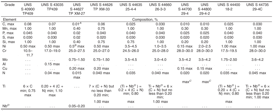
9.1.1 The steel shall conform to the chemical composition in Table 1.
TABLE 1 Chemical Requirements
A For small diameter or thin walls, or both, tubing, where many drawing passes are required, a carbon maximum of 0.015 % is necessary. Small outside diameter tubes are defined as those less than 0.500 in. [12.7 mm] in outside diameter and light wall tubes as those less than 0.049 in. [1.2 mm] in average wall thickness (0.040 in. [1mm] in minimum wall thickness).
B Nickel + copper.
C Carbon + nitrogen = 0.025 max.
D The term Niobium (Nb) and Columbium (Cb) are alternate names for the same element.
9.1.2 When specified on the purchase order, a product analysis shall be supplied from one tube or coil of steel per heat. The product analysis tolerance of Specification A480/A480M shall apply.
9.1.3 If the original test for product analysis fails, retests of two additional lengths of flat-rolled stock or tubes shall be made. Both retests, for the elements in question, shall meet the requirements of this specification; otherwise all remaining material in the heat or lot shall be rejected or, at the option of the producer, each length of flatrolled stock or tube may be individually tested for acceptance. Lengths of flat-rolled stock or tubes that do not meet the requirements of this specification shall be rejected.
10. Mechanical Requirements
10.1 Tensile Properties:
10.1.1 The material shall conform to the tensile properties shown in Table 2.
TABLE 2 Tensile Requirements
| Grade |
Tensile Strength, min, ksi [MPa] |
Yield Strength, min, ksi [MPa] |
Elongation A in 2 in.or 50 mm,min, % |
| TP 409 | 55 [380] | 30 [205] | 20 |
| TP 439 | 60 [415] | 30 [205] | 20 |
| TP XM-27 | 65 [450] | 40 [275] | 20 |
| TP XM-33 | 68 [470] | 45 [310] | 20 |
| 25-4-4 | 90 [620] | 75 [515] | 20 |
| 26-3-3 | 85 [585] | 65 [450] | 20 |
| 29-4 | 80 [550] | 60 [415] | 20 |
| 29-4-2 | 80 [550] | 60 [415] | 20 |
| 18-2 | 60 [415] | 35 [240] | 20 |
| 29-4C | 75 [515] | 60 [415] | 18 |
A For longitudinal strip tests, a deduction of 0.90 % for 29-4C and 1 % for all other grades shall be made from the basic minimum elongation for each 1 ⁄ 32 in. [0.8 mm] decrease in wall thickness below 5 ⁄ 1 6 in. [8 mm]. Table 3 gives the computed minimum values.
TABLE 3 Minimum Elongation Values A
| Wall Thickness B | Elongation in 2 in. or 50 mm,min, % | ||
| in. | mm | 29-4C | All Other |
| 5 ⁄ 1 6 (0.312) | 8 | 18 | 20 |
| 9 ⁄ 32 (0.281) | 7.2 | 17 | 19 |
| 1 ⁄ 4 (0.250) | 6.4 | 16 | 18 |
| 7 ⁄ 32 (0.219) | 5.6 | 15 | 17 |
| 3 ⁄ 1 6 (0.188) | 4.8 | 14 | 16 |
| 5 ⁄ 32 (0.156) | 4 | 13 | 15 |
| 1 ⁄ 8 (0.125) | 3.2 | 13 | 14 |
| 3 ⁄ 32 (0.094) | 2.4 | 12 | 13 |
| 1 ⁄ 1 6 (0.062) | 1.6 | 11 | 12 |
| 0.062 to 0.035, excl | 1.6 to 0.9 | 10 | 12 |
| 0.035 to 0.022, excl | 0.9 to 0.6 | 10 | 11 |
| 0.022 to 0.015, excl | 0.6 to 0.4 | 10 | 11 |
A Calculation elongation shall be rounded to the nearest whole number.
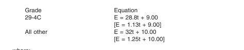
B Where the wall thickness lies between two values shown above, the minimum elongation value shall be determined by the following equation:
where:
E = elongation in 2 in. or 50 mm, %, and
t = actual thickness of specimen, in. [mm].
10.1.2 One tension test shall be made on a specimen for lots of not more than 50 tubes. Tension tests shall be made on specimens from two tubes for lots of more than 50 tubes.
10.1.3 Table 3 gives the computed minimum elongation values for each 1 ⁄ 32 in. [0.8 mm] decrease in wall thickness.
10.2 Hardness:
10.2.1 The tubes shall have a hardness number not to exceed those prescribed in Table 4. This hardness requirement is not to apply to the bend area of U-bend tubes which are not heat treated after bending.
TABLE 4 Hardness Requirements
| Grade | Brinell Hardness, max | Rockwell Hardness,B Scale,max |
| TP 409 | 207 | 95 |
| TP 439 | 207 | 95 |
| P XM-27 | 241 | 100 |
| TP XM-33 | 241 | 100 |
| 25-4-4 | 270 | 27 A |
| 26-3-3 | 265 | 25 A |
| 29-4 | 241 | 100 |
| 29-4-2 | 241 | 100 |
| 18-2 | 217 | 95 |
| 29-4C | 241 | 100 |
A Rockwell Hardness, C scale.
10.2.2 Brinell or Rockwell hardness tests shall be made on specimens from two tubes from each lot.
10.3 Reverse Flattening Test (for Welded Product)—One reverse flattening test shall be made on a specimen from each 1500 ft [460 m] of finished tubing.
10.4 Flange Test (for Welded Product)—Flange tests shall be made on specimens from each end of one finished tube, not the one used for the flattening test, from each lot.
10.5 Flaring Test (for Seamless Tubes)—One test shall be made on specimens from one end of one tube from each lot of finished tubes. The minimum expansion of the inside diameter shall be 10 %.
10.6 Pressure Test—Each straight tube, or each U-tube after completion of the bending and post-bending heat treatment,shall be pressure-tested in accordance with one of the following paragraphs as specified by the purchaser:
10.6.1 Hydrostatic Test—Each tube shall be given an internal hydrostatic test in accordance with Specification A1016/A1016M.
10.6.2 Pneumatic Test—Each tube shall be examined by a pneumatic test (either air underwater or pneumatic leak test) in accordance with Specification A1016/A1016M.
10.7 Lot Definitions:
10.7.1 For flange and flaring test requirements, the term“lot” applies to 125 tube groupings, prior to cutting to length,ofthe same nominal size and wall thickness, produced from the same heat of steel and annealed in a continuous furnace.
10.7.2 For tension and hardness requirements, the term “lot”applies to all tubes, prior to cutting to length, of the same nominal diameter and wall thickness, produced from the same heat of steel and annealed in a continuous furnace at the same temperature, time at temperature, and furnace speed.
11. Corrosion Resisting Properties
11.1 One full section sample 1 in. [25 mm] long from the center of a sample tube of the smallest radius bend that is heat treated shall be tested in the heat treated condition in accordance with the appropriate practice in Practices A763 for the specified grade, or as agreed upon for TP409.
11.2 One full-section sample 1 in. [25 mm] long from each lot of straight tubes shall be tested in the finished condition in accordance with the appropriate practice in Practices A763 for the specified grade, or as agreed upon for TP409.
11.3 The appearance of any fissures or cracks in the test specimen, when evaluated in accordance with the Evaluation Sections of Practices A763 indicating the presence of intergranular attack, shall be cause for rejection of that lot.
11.4 For corrosion test requirements, the term “lot” applies to all tubes, prior to cutting to length, of the same nominal diameter and wall thickness, produced from the same heat of steel and annealed in a continuous furnace at the same temperature, time at temperature, and furnace speed.
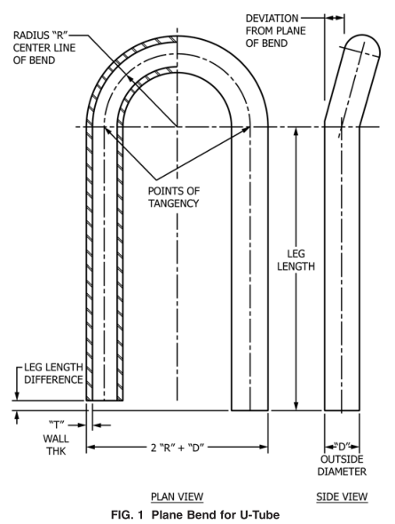
12. Permissible Variations in Dimensions (Fig. 1)
12.1 Permissible variations from the specified outside diameter shall be in accordance with Specification A1016/A1016M.Those tolerances do not apply to the bent portion of the U-tubes. At the bent portion of a U-tube for R = 2 × D or greater, neither the major nor minor diameter of the tube shall deviate from the nominal diameter prior to bending by more than 10 %. If less than 2 × D is specified, tolerances could be greater.
12.2 Permissible Variations from the Specified Wall Thickness:
12.2.1 Permissible variations from the specified minimum wall thickness shall not exceed +20 − 0 %.
12.2.2 Permissible variations from the specified average wall thickness are 610 % of the nominal wall thickness.
12.2.3 The wall thickness of the tube in the U-bent section shall not be less than value determined by the equation:
where:
t f = wall thickness after bending, in. [mm],
T = specified minimum tube wall thickness, in. [mm],
R = centerline bend radius, in. [mm], and
D = nominal outside tube diameter, in. [mm].
12.3 Permissible Variations from the Specified Length:
12.3.1 Straight Lengths—The maximum permissible variations for lengths 24 ft [7.3 m] and shorter shall be + 1 ⁄ 8 in. [+3mm], −0; for lengths longer than 24 ft [7.3 m], an additional over tolerance of + 1 ⁄ 8 in. [+3 mm] for each 10 ft [3 m], or fraction thereof, shall be permitted up to a maximum of + 1 ⁄ 2 in.[+13 mm].
12.3.2 U-Bends—In the case of U-tubes, the length of the tube legs, as measured from the point of tangency of the bend and the tube leg to the end ofthe tube leg, shall not be less than specified, but may exceed the specified values by the amount given in Table 5. The difference in lengths ofthe tube legs shall not be greater than 1 ⁄ 8 in. [3 mm] unless otherwise specified.
TABLE 5 Tube Leg Length Tolerance
| Leg Length, ft [m] | Plus Tolerance, in. [mm] |
| Up to 20 [6], incl | 1 ⁄ 8 [3.2] |
| Over 20 to 30 [6 to 9], incl | 5 ⁄ 32 [4.0] |
| Over 30 to 40 [9 to 12], incl | 3 ⁄ 1 6 [4.8] |
12.4 The end of any tube may depart from square by not more than the amount given in Table 6.
TABLE 6 Squareness of Ends Tolerance
| Tube OD, in. [mm] | Tolerance, in. [mm] |
| Up to 5 ⁄ 8 [15.9], incl | 0.010 [0.25] |
| Over 5 ⁄ 8 to 1 in. [15.9 to 25.4], incl | 0.016 [0.41] |
12.5 The leg spacing measured between the points of tangency of the bend to the legs shall not vary from the value (2R-specified tube outside diameter) by more than 1 ⁄ 16 in. [1.5 mm] where R is the center-line bend radius.
12.6 The bent portion of the U-tube shall be substantially uniform in curvature, and not to exceed 6 1 ⁄ 16 in. [61.5 mm] of the nominal center-line radius.
12.7 Permissible deviation from the plane of bend (see Fig.1) shall not exceed 1 ⁄ 16 in. [1.5 mm] as measured from the points of tangency.
13. Workmanship, Finish, and Appearance
13.1 Tubing purchased to this specification is intended for use in heat exchangers and will be inserted through closefitting holes in baffles or support plates, or both, spaced along the tube length. The tube ends will also be inserted into very close-fitting holes in a tubesheet and expanded and may be welded therein. The tubes shall be able to stand roll expanding (See Note 1) and bending without showing cracks and flaws,and shall be finished reasonably straight and suitable for the intended purpose. Surface defects that violate minimum wall requirements shall be cause for rejection.
NOTE 1—Ferritic stainless steels may be expanded by other methods but the user should exercise precautions when using methods other than roll expansion as these grades have a higher ductile-brittle transition temperature, are more strain rate sensitive, and have lower ductility than austenitic grades.
13.2 The residual chloride salt contamination of the inside and outside surface of the tubing at the time of packing for shipment from the mill shall not exceed a concentration of 1 mg/ft 2 [10.7 mg/m 2 ] of tube surface. One tube in each 500 pieces shall be checked immediately prior to packing for shipment for chloride salt contamination by a procedure agreed to between the manufacturer and purchaser.
14. Surface Condition
14.1 The straight tubes, after final annealing, shall be pickled using a solution of nitric and hydrofluoric acids followed by flushing and rinsing in water. Ifbright-annealing is performed, this requirement does not apply.
14.1.1 All tubes shall be free of excessive mill scale,suitable for inspection. Aslight amount ofoxidation will not be considered as scale. Any special finish requirements shall be subject to agreement between the manufacturer and the purchaser.
14.2 A light oxide scale on the outside surface of U-bend area shall be permitted for tubes that have been electricresistance heat treated after bending.
15. Nondestructive Test (Electric Test)
15.1 Each straight tube shall be tested after the finish heat treatment by passing it through a nondestructive tester capable of detecting defects on the entire cross section of the tube in accordance with Specification A1016/A1016M.
16. Inspection
16.1 The inspector representing the purchaser shall have entry, at all times, to those areas where inspection and testing is being performed on the purchaser’s ordered material. The manufacturer shall afford the inspector all reasonable facilities to satisfy the inspector that the material is being furnished in accordance with this specification. All required tests and inspections shall be made at the place of manufacture prior to shipment, unless otherwise specified, and shall be conducted so as not to interfere unnecessarily with the operation of the works.
17. Rejection
17.1 Each length of tubing received from the manufacturer may be inspected by the purchaser, and, if it does not meet the requirements of the specification based on the inspection and test method outlined in the specification, the tubing may be rejected and the manufacturer shall be notified. Disposition of rejected tubing shall be a matter of agreement between the manufacturer and the purchaser.
17.2 Material that fails in any of the forming operations or in the process of installation and is found to be defective, shall be set aside, and the manufacturer shall be notified. Disposition of such material shall be a matter for agreement between the manufacturer and the purchaser.
18. Certification
18.1 A test report, signed by an authorized employee or representative of the manufacturer, shall be furnished to the purchaser to indicate the specification and grade, seamless or welded, the results of the heat analysis, hardness, and tensile properties. Product analysis will be reported only when requested on the purchase order as provided in 9.1.1.
19. Product Marking
19.1 All tubes shall be marked with the heat number.
19.2 Containers and packages shall be marked or tagged to show the purchaser’s order number, the manufacturer’s order number, specification, seamless or welded, grade, size and wall thickness, minimum or average, number of pieces contained in the package, and item number (if appropriate).
20. Packaging
20.1 All tubing shall be packaged and blocked in such a manner as to prevent damage in ordinary handling and transportation. The boxes shall be constructed in such a manner that no nails, staples, screws, or similar fasteners are required to close and secure the box after the tubes have been placed in the box. The box shall be lined with plastic sheet or vapor barrier materials so as to prevent chloride contamination of the tube during handling, transportation, and storage.
20.2 The U-bent tubes shall be arranged in boxes so that the smaller radius bends may be removed without disturbing larger radius bends. Tubes for an item number shall be boxed together.
21. Keywords
21.1 feedwater heater tubes; ferritic stainless steel; seamless steel tube; stainless steel tube; steel tube; welded steel tube